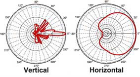
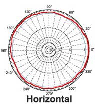
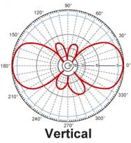
FAQ & Terminology WLAN


Beamwidth

This is a measurement parameter of the antenna's radiation pattern. It is defined as the -3dB points (relative to the direction with the highest gain) where the intensity falls off by ½ (half) power. It is measured in degrees, representing an angular measurement of how wide the pattern is dispersed. Because the RF radiation is 3-dimensional, it is usually measured in two angular directions, azimuth (horizontal) and elevation (vertical).

Example: Parabolic antennas have very high gain over a very narrow beamwidth, usually less than
5 degrees in azimuth.

Download:
Distance Calculator
(XLS)

Directional Antenna

It is an antenna that designed to be pointed in a certain direction by the user. They are usually much higher in gain, at the expense of having to physically adjust them so that they point correctly at the corresponding receiving (or transmitting) radio.


Antenna pattern of a directional antenna, with 5 degrees vertical beamwidth and 90 degrees horizontal beamwidth.

Bundling of the transmit energy into one direction allows increase of the gain and therefore extension of the operation range of the antenna.


Omni-directional Antenna


It is an antenna that sends or receives signals equally in all directions (horizontal).

The horizontal antenna pattern of an omnidirectional antenna is shown here.

The vertical antenna pattern depends on type of antenna. There are antennas without any gain (isotropic radiator), 3 dBi up to
13 dBi gain. The higher the gain the lower the vertical beamwidth and the better the overall efficiency of the antenna.


Directivity

It is a measure of how focused an antenna coverage pattern is in a given direction. A theoretical loss-less antenna element, referred to as a isotropic element, has 0 dBi directive gain equally distributed in all 3 dimensions. In order to achieve higher directive gain, antennas are normally designed to focus or concentrate the antenna pattern only in the direction of the radio link, thereby maximizing energy usage.

Example: Patch antennas have a beam pattern directed in only one direction, focusing much of their energy normal to the plane of their application.

Gain

This parameter is used to compare different antenna radiation characteristics. Unlike directivity, this parameter takes into account both the directive property of the antenna, as well as how efficiently it transforms available input power into radiated power. It is usually measured in units of dBi (decibels as referenced to an isotropic antenna element) or dBd (decibels as referenced to a dipole antenna element, where 0 dBd = 2.1 dBi). An isotropic antenna is a theoretical point source radiating equal power in all directions, resulting in a perfect spherical pattern. This ideal reference point is defined to be 0 dBi. New antenna designs are usually compared to this common reference level.

Example: Some bar omni-directional antennas have about 1.5 dBi gain in the horizontal plane, meaning they have 1.5 dB more gain than an isotropic antenna would have in the horizontal plane.

Pattern

Related to directivity, it is description of an 3-Dimensional shape of the antenna's radiation field. It is sometimes subjectively described by how it looks, but it is usually objectively measured in azimuthal and elevation plots. Plots of gain vs. direction show 2-Dimensional cuts in different planes of the 3-D total shape.


The pictures show antenna pattern of an omnidirectional antenna (360° coverage horizontal) with 40° vertical beamwidth.

The vertical beamwidth angle is defined by the intersection point of pattern(red) and -3dB curve (blue) - see vertical pattern.


Polarization

It is the figure traced out in time by the instantaneous electric field vector associated with the radiation field produced by an antenna. Electromagnetic waves in free space travel in a direction that is perpendicular to the direction(s) of oscillation of the electric and magnetic fields. For example, if an RF wave is traveling in the z-direction, the electric field could be oscillating in either (or both) the x- and y-directions (referred to as the horizontal and vertical directions).

Examples: (1) RF waves can be separated into vertical-only and horizontal-only polarized waves, both of which are a type of linear polarization. (2) Satellite signals are often circularly polarized, having both vertical and horizontal components rotating around the z-direction of wave propagation.

Return Loss

The difference between the power input to and the power reflected from a discontinuity in a transmission circuit. This parameter is often expressed as the ratio in decibels of the power incident on the antenna terminal to the power reflected from the terminal at a particular frequency or band of frequencies.

Example: Antennas often are designed to have a return loss of -10dB or less, meaning that at least 90% of the electrical energy generated by the radio is actually transferred into electromagnetic wave energy.

Voltage Standing Wave Ratio (VSWR)

Is another way to measure return loss. It is a ratio of the maximum to minimum amplitude (or the voltage or current) of the corresponding field components appearing on a line that feeds an antenna.

Examples: Antennas are designed to have a VSWR of 2.0:1 or less, meaning that at least 90% of the electrical energy generated by the radio is actually transferred into electromagnetic wave energy. Return loss of -9.6 dB is equivalent to a 2.0:1 (VSWR).