|
|

|
|
|
|
Glossary WLAN
|
|
|
AP
Access Point - connects wireless devices to another network (e.g. Internet)
Beamwidth
This is a measurement parameter of the antenna's radiation pattern. It is defined as the -3dB points (relative to the direction with the highest gain) where the intensity falls off by ½ (half) power. It is measured in degrees, representing an angular measurement of how wide the pattern is dispersed. Because the RF radiation is 3-dimensional, it is usually measured in two angular directions, azimuth (horizontal) and elevation (vertical).
Example: Parabolic antennas have very high gain over a very narrow beamwidth, usually less than
5 degrees in azimuth.
|
|
Download:
Distance Calculator
(XLS)
|
Bluetooth
Technology designed for short-range, wireless communications among computing devices and mobile products, including PCs and laptop computers, PDAs, printers, and mobile phones. In Designed as a cable-replacement, Bluetooth enables short-range transmission of voice and data in the 2.4 GHz frequency spectrum within a range of about 30 feet.
|
|
Capacity - Access Point
The number of simultaneous users that an access point can support depends mostly on the amount of data traffic at the time (heavy versus light downloads and uploads). Bandwidth is shared among users on a WLAN as with wired network connections. Network performance, as gauged by the number of simultaneous users, hinges on the combined computing activity. For example, in 802.11b, each hardware access point has up to 11 Mbps throughput. This capacity is adequate for:
- 50 nominal users who are mostly idle and check an occasional text based e-mail.
- 25 mainstream users who use a lot of e-mail and download or upload moderately sized files.
- 10 to 20 power users who are constantly on the network and deal with large files.
To increase capacity, more access points may be added, which gives users more opportunity to enter a network. Networks are optimized when the access points are set to different channels. For instance, a company may place three 802.11b access points (with a range of up to 100 meters each) in three adjacent offices, with each unit set to a different channel. In theory, many users could then share up to 33 Mbps total capacity (although no single user would ever have throughput faster than 11 Mbps). In reality, clients associate with the access point with which they share the strongest signal, so the bandwidth may not be dispersed evenly among users
|
|
Channel
Channelsaffect the overall capacity of the WLAN. A channel represents a narrow band of radio frequency. Since radio frequency modulates within a band of frequencies, there is limited amount of bandwidth within any given range to carry data. It is important that the frequencies do not overlap or else the throughput would be significantly lowered as the network sorts and reassembles the data packets sent over the air.
Knowing that the 802.11a specification operates at radio frequencies between 5.15 and 5.875 GHz, and the 802.11b and 802.11g specification operates at radio frequencies in the 2.4 to 2.497 GHz range, we can see that the 802.11a has a wider frequency band, allowing more channels and more overall throughput. The wider frequency band allows 802.11a to support up to eight non-overlapping channels and 802.11b/g to support up to three non-overlapping channels. The frequency ranges and channels may vary by country.
Each channel will carry a maximum throughput for its standard. Therefore, the 802.11b and 802.11g standards have a maximum of three non-overlapping channels carrying 11 Mbps throughput each (33 Mbps total) and 54 Mbps (162 Mbps total) throughput. The 802.11a standard has a maximum of eight non-overlapping channels carrying 54 Mbps throughput each, or 432 Mbps total throughput.
|
|
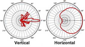
Directional Antenna
It is an antenna that designed to be pointed in a certain direction by the user. They are usually much higher in gain, at the expense of having to physically adjust them so that they point correctly at the corresponding receiving (or transmitting) radio.
|
|
|
Antenna pattern of a directional antenna, with 5 degrees vertical beamwidth and 90 degrees horizontal beamwidth.
Bundling of the transmit energy into one direction allows increase of the gain and therefore extension of the operation range of the antenna.
|
|
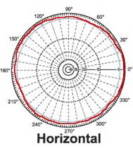
Omni-directional Antenna
|
|
|
It is an antenna that sends or receives signals equally in all directions (horizontal).
The horizontal antenna pattern of an omnidirectional antenna is shown here.
The vertical antenna pattern depends on type of antenna. There are antennas without any gain (isotropic radiator), 3 dBi up to
13 dBi gain. The higher the gain the lower the vertical beamwidth and the better the overall efficiency of the antenna.
|

|
|
Directivity
It is a measure of how focused an antenna coverage pattern is in a given direction. A theoretical loss-less antenna element, referred to as a isotropic element, has 0 dBi directive gain equally distributed in all 3 dimensions. In order to achieve higher directive gain, antennas are normally designed to focus or concentrate the antenna pattern only in the direction of the radio link, thereby maximizing energy usage.
Example: Patch antennas have a beam pattern directed in only one direction, focusing much of their energy normal to the plane of their application.
Gain
This parameter is used to compare different antenna radiation characteristics. Unlike directivity, this parameter takes into account both the directive property of the antenna, as well as how efficiently it transforms available input power into radiated power. It is usually measured in units of dBi (decibels as referenced to an isotropic antenna element) or dBd (decibels as referenced to a dipole antenna element, where 0 dBd = 2.1 dBi). An isotropic antenna is a theoretical point source radiating equal power in all directions, resulting in a perfect spherical pattern. This ideal reference point is defined to be 0 dBi. New antenna designs are usually compared to this common reference level.
Example: Some bar omni-directional antennas have about 1.5 dBi gain in the horizontal plane, meaning they have 1.5 dB more gain than an isotropic antenna would have in the horizontal plane.
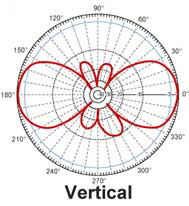
Pattern
Related to directivity, it is description of an 3-Dimensional shape of the antenna's radiation field. It is sometimes subjectively described by how it looks, but it is usually objectively measured in azimuthal and elevation plots. Plots of gain vs. direction show 2-Dimensional cuts in different planes of the 3-D total shape.
|
|
|
The pictures show antenna pattern of an omnidirectional antenna (360° coverage horizontal) with 40° vertical beamwidth.
The vertical beamwidth angle is defined by the intersection point of pattern(red) and -3dB curve (blue) - see vertical pattern.
|
|
Polarization
It is the figure traced out in time by the instantaneous electric field vector associated with the radiation field produced by an antenna. Electromagnetic waves in free space travel in a direction that is perpendicular to the direction(s) of oscillation of the electric and magnetic fields. For example, if an RF wave is traveling in the z-direction, the electric field could be oscillating in either (or both) the x- and y-directions (referred to as the horizontal and vertical directions).
Examples: (1) RF waves can be separated into vertical-only and horizontal-only polarized waves, both of which are a type of linear polarization. (2) Satellite signals are often circularly polarized, having both vertical and horizontal components rotating around the z-direction of wave propagation.
Range and Performance
The speed at which a WLAN performs depends on many things, from the efficiency of the wired network to the configuration of the building to the type of WLAN employed. As a general rule for all WLANs, data throughput decreases as the distance between the WLAN access point and the wireless client increases.
The 802.11 standards support multiple data rates to accommodate the loss of signal strength while maintaining high quality in data packet reassembly. The WLAN client constantly performs operations to detect and automatically set the best possible speed. Subsequently, data rates may be listed as a series of numbers (such as 11, 5.5, 2, 1 Mbps for 802.11b at various ranges) to correspond to throughput at various ranges.
The frequency at which 802.11b and 802.11g is transmitted allows it to penetrate solid materials allowing, in most indoor environments, a maximum range of 300 feet. 802.11a experiences a steeper decline in throughput as distance increases from the access point and has a maximum range of about 150 feet in most indoor environments. The range and transmission speed is affected by the environment in which the WLAN is deployed.
|
|
Return Loss
The difference between the power input to and the power reflected from a discontinuity in a transmission circuit. This parameter is often expressed as the ratio in decibels of the power incident on the antenna terminal to the power reflected from the terminal at a particular frequency or band of frequencies.
Example: Antennas often are designed to have a return loss of -10dB or less, meaning that at least 90% of the electrical energy generated by the radio is actually transferred into electromagnetic wave energy.
SSID
A unique 32-character network name, or identifier, that differentiates one wireless LAN from another. All access points and clients attempting to connect to a specific WLAN must use the same SSID. The SSID can be any alphanumeric entry up to a maximum of 32 characters.
Voltage Standing Wave Ratio (VSWR)
Is another way to measure return loss. It is a ratio of the maximum to minimum amplitude (or the voltage or current) of the corresponding field components appearing on a line that feeds an antenna.
Examples: Antennas are designed to have a VSWR of 2.0:1 or less, meaning that at least 90% of the electrical energy generated by the radio is actually transferred into electromagnetic wave energy. Return loss of -9.6 dB is equivalent to a 2.0:1 (VSWR).
WiFi Certified TM
The certification standard designating IEEE 802.11-based wireless local area network (WLAN) products that have passed interoperability testing requirements developed and governed by the Wi-Fi Alliance.
Wi-Fi ®
Short for wireless fidelity. A term developed by the Wi-Fi Alliance to describe wireless local area network (WLAN) products that are based on the Institute of Electrical and Electronics Engineers’ (IEEE) 802.11 standards.
Wi-Fi® and the Wi-Fi logo are registered trademarks of the Wi-Fi Alliance
|
|
|